
FAQ
Browse common CAE product, ordering, and support questions by section.
If you have any problems fitting our products please browse the FAQ's below.
If you can't find the answer here don't hesitate to call CAE on 03 5472 1442.
If you don't have a copy of the instructions you can download it on
EFI Loom ECU or PCM Frequently Asked Questions
18 questions
What do I do if the OBD (On Board Diagnostic) Scanner displays a P1336 (Crankshaft position (CKP) system variation not learned) code.
This re-learn procedure can be done by any GM Holden dealer via their Tech II programmer. For engine conversions the dealer may require donor vehicle original V.I.N. (Vehicle Identification Number) for dealer to gain access. This only applies to Holden Vehicles Manufactured in Australia.
This diagnostic code will disable the misfire monitor, and not warn the driver that the engine has entered a dangerous misfire event, which can cause catalyst damage & higher than usual emission readings.
This code should not effect the overall vehicle operation, and should not disable engine in any way.
System Scan: If encountering problems such as engine management light staying on, automatic transmission not shifting properly, speedo not working etc.
Where do I mount ECU? (Computer)
Cable-x not working?
2) If connecting direct from PCM (Computer) speedo signal you need to use a 4.7k ohm pull up resistor.
3) Read instructions supplied in box and set the trim switches accordingly.
Auto Trans goes in to 3rd only.
Fuel pump not working.
Cranking issues.
Engine cranks and fires on start but cuts out when key is released.
Engine starts and runs but will not rev over 2000rpm and cuts out.
Vehicle fires but cuts out within 2 seconds
Speedo and Tacho not working.
2) Depending on Speedo brand it may need 4.7k ohm pull-up resistor.
Pedal not working with TAC module.
AC re-gassed but still not switching by switch.
GENIII loom into a VN had no positive feed into ECM (Computer).
Transmission not shifting gears
Where do I fit temp. and oil sender's for my gauges on a LS1 - LS2 - LS3 - LS7?
What Senders do we use to get factory oil and temp. gauges to work on a new engine transplant?
Which sump do I use on my VB to VS LS-1 LS-2 engine conversion?
FUEL TANK MODIFICATIONS
1 question
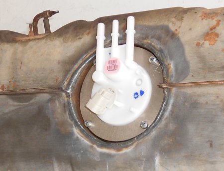
How do I fit an in-tank fuel pump in my old tank?
You will need to remove the old tank and determine where there is room to
fit the pump. Make sure that the pump pick-up will sit on the bottom of the
tank, if not full capacity will not be utilised. If possible retain the original
fuel sender and make sure new assembly does not interfere with it.
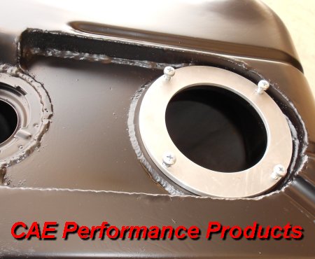
CAE can supply either Mild Steel, Aluminium or Stainless Steel weld rings.
You will have to position the weld ring and then cut the hole using a hols saw.
Next you prepare the tank for welding.
CAUTION: welding fuel tank is dangerous if you don't have any experience don't do it)
If you don't have the expertise to do this job CAE can do these modifications
for you just call us on 03 5472 1442.
More information about our Fuel Systems here.
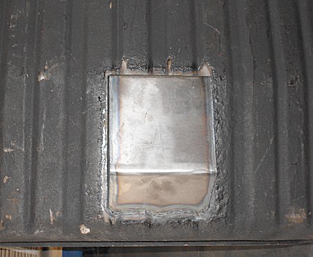
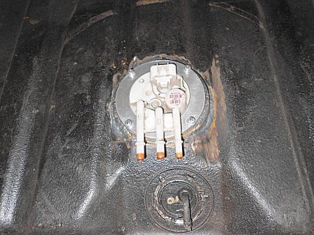
Holden HQ-WB tank requires modification to top and bottom so the EFI pump will fit.
Wiper Motor F.A.Q. Wiper Arm and Blades F.A.Q.
4 questions
10" Flat Screen Blade.
10" Flat Screen Blade.
18" Curved Screen Blades.
Working out the correct length of the Arm and Blade.
Adjusting the Wiper Arm Sweep Angle.
1 question
Can I change the Angle of Sweep.
Adjusting the Wiper Arm Park Position.
4 questions
A - Park Position of the Wiper Blades.
B - On Cable Drive Wipers (Horizontal Parking)
C - On Cable Drive Wipers (Clap-hands Type Parking i.e. both Blades pointing towards each other)
D - On Mechanical Arm Drive Wipers
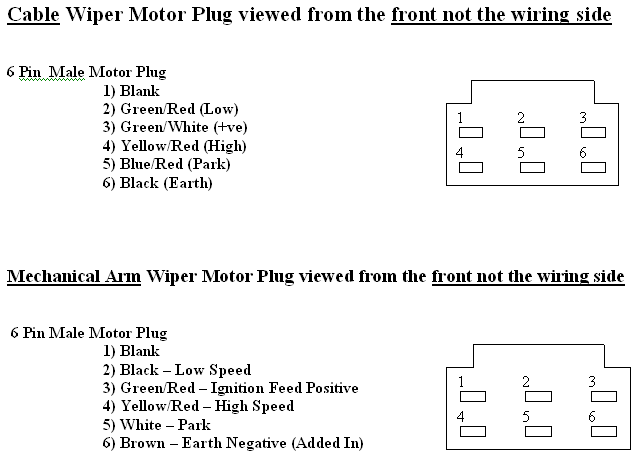
Wiper Motor Wiring.
2 questions
Wiper Wiring.
All CAE Wipers are fitted with a standard 6 Pin Wiring Plug as per diagram below: --
Wiper Mounting Bracket
1 question
Mount bracket does not suit my application.
57Chev Pivot Posts
1 question
Are there longer Posts available?
Spiral Drive Cables
1 question
How long can the spiral drive cable be, in the Cable drive kits?
Fitting a Brake Disc and Caliper Conversion Kit Click for larger image
1 question
Fitting a Brake Disc and Caliper Conversion Kit Click for larger image
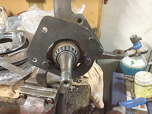
This image shows the adaptor brackes fitted to the stub.
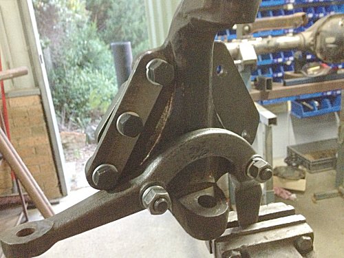
This is from the back side.
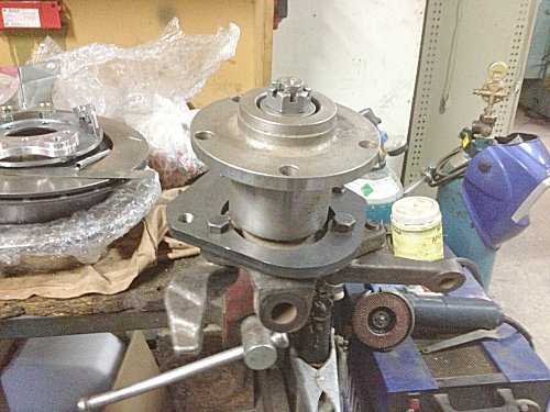
Hub is fitted in the usual way.
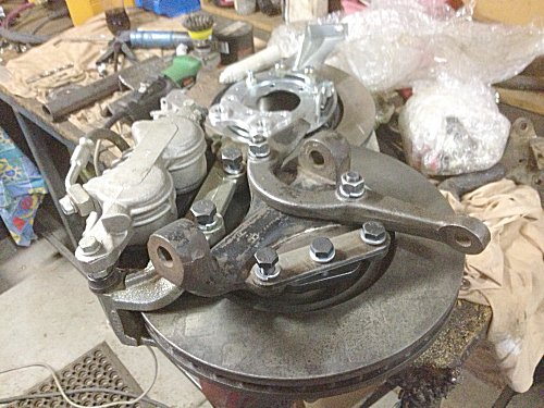
This shows the complete assembly from the back.
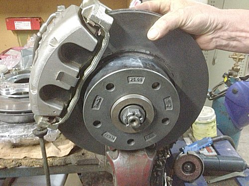
Job done.
Hi-Torque Starter F.A.Q.
1 question
How do I set-up a remote starter solenoid for FE engine in a Ford, Mustang to Thunderbird's etc. and most early English vehicles.
1.. Move the large primary cable from the switched side of the solenoid to the 'always hot or live' side of the solenoid. In other words, the large cable running from the solenoid on the support panel to the starter should be placed on the same pole of the solenoid as the large cable running to the battery. You should have enough bolt thread showing to achieve this. Or get a new cable to connect the starter to the positive lead on battery. You must leave the cable from the battery to remote solenoid, 2-cables doesn't look as neat.
2.. Make up a lighter gauge (say 4mm) wire to run from the switched side of the solenoid (where you just moved the large cable from!) down to the small terminal pole on the starter. Use a ring terminal at the solenoid end of the wire and spade terminal at the starter end of the wire. MAKE SURE THAT THE TERMINAL ON THE STARTER END DOES NOT CONTACT THE PRIMARY CABLE OR TERMINAL. FAILURE TO DO SO WILL RESULT IN STARTER 'RUN ON' AND WILL RUIN BOTH THE STARTER AND THE FLYWHEEL/FLEXPLATE.
3.. Secure the new small wire to the primary cable with zip-ties, tape, or wire sheathing to protect it from moving parts, heat and foreign object damage.
Click for Diagram
Hi-Torque Starter - How to measure the OUTER MESH
1 question
How to measure the OUTER MESH
Correct pinion & ring gear clearance is needed before starting the engine. If this is not correct, damage will occur. With the starter motor disengaged and mounted correctly, the pinion to ring gear clearance (Outer mesh) should be 2 to 2.5mm See figure 1
Before fitting the Starter measured from the Contact Edge of Drive Plates Ring Gear to the Front Edge of the Starter Pinion in stationary Position. See Fig. 1
To Calculate the Outer Mesh measure the distance from the Starter mounting face to the front side of the ring gear. A Then measure the Starter mounting face to the end of the pinion. B The difference between measurement A and B is the Pinion Ring Gear clearance C
A.................... - B.................... = C
If this is less than 2mm then the shim spacers will be needed. Shims are available on request.
No FAQ entries match the current filters.